SIM Electrical Module
With the Electrical Bus Module the Electrical supply and in-plant distribution system can be modeled as an "intelligent" screen where each model component is linked to its bus. Individual buses (breakers) can be failed to fail all components on the failed bus. The feed to the next lower bus is also failed, and if no other feed exists for the lower bus it will fail and its components will also fail.
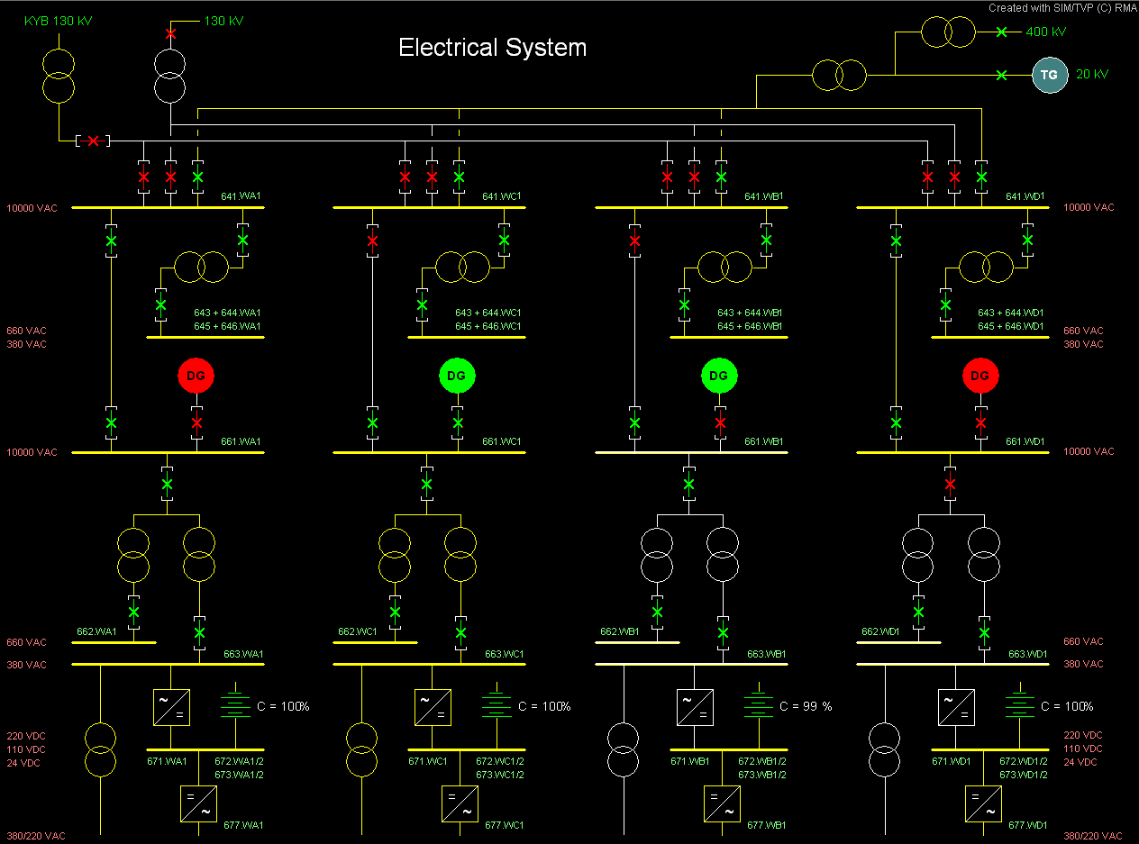
The sample screen shows four Divisions, A, B, C, D, each in a different failure state:
- Division A (left): Normal operating condition
- Division B: 10,000 Volt Feed Breaker is failed open. Diesel Generator started and Diesel Supply Breaker closed.
- Division C: 10,000 Volt Feed Breaker is failed open. Diesel Generator started but Diesel Supply Breaker failed to open
- Division D (right): 10,000 Volt Feed Breaker below Diesel Generator bus is failed open. Battery supplies DC Buses.
Legend:
- Yellow Buses are active, white buses are without power
- Green Breakers are closed, red breakers are open
- Green Diesel Generator is running, red Diesel Generator is not running
- All components in the model are linked to their supply bus.
Sample Electrical Screen